  |
| Complete Assembly |
- The Table
- X Axis
- Y Axis
- Z Axis
Main dimensions:
- length = 1520mm
- width = 1553mm
- min. height = 1493mm
- max. height = 1783mm
3D and 2D drawings can be found here...
Please let me know your opinions about it.
  | |
| 1. Table |
In order to get good precision with a Tooling machine all parts needs to be as rigid as possible.
So I tried to make the table not to bend under the load. That's why I designed it with eight sliding linear blocks.
I also thought to put a five mm carbon steal plate with some holes which is quite cheap... but "on paper" the whole plate will be around 80kg so it's not a solution yet.
So for this reasons I decided to use a special marine plywood with nuts on the other side for fixing the part which is machined. (this is not showed in my drawing yet but I will put some picture with the plate when it will be build)
The theoretical weight of this table is 83kg.
Main dimensions:
- length = 1520mm
- width = 1320mm
- height = 294mm
  |
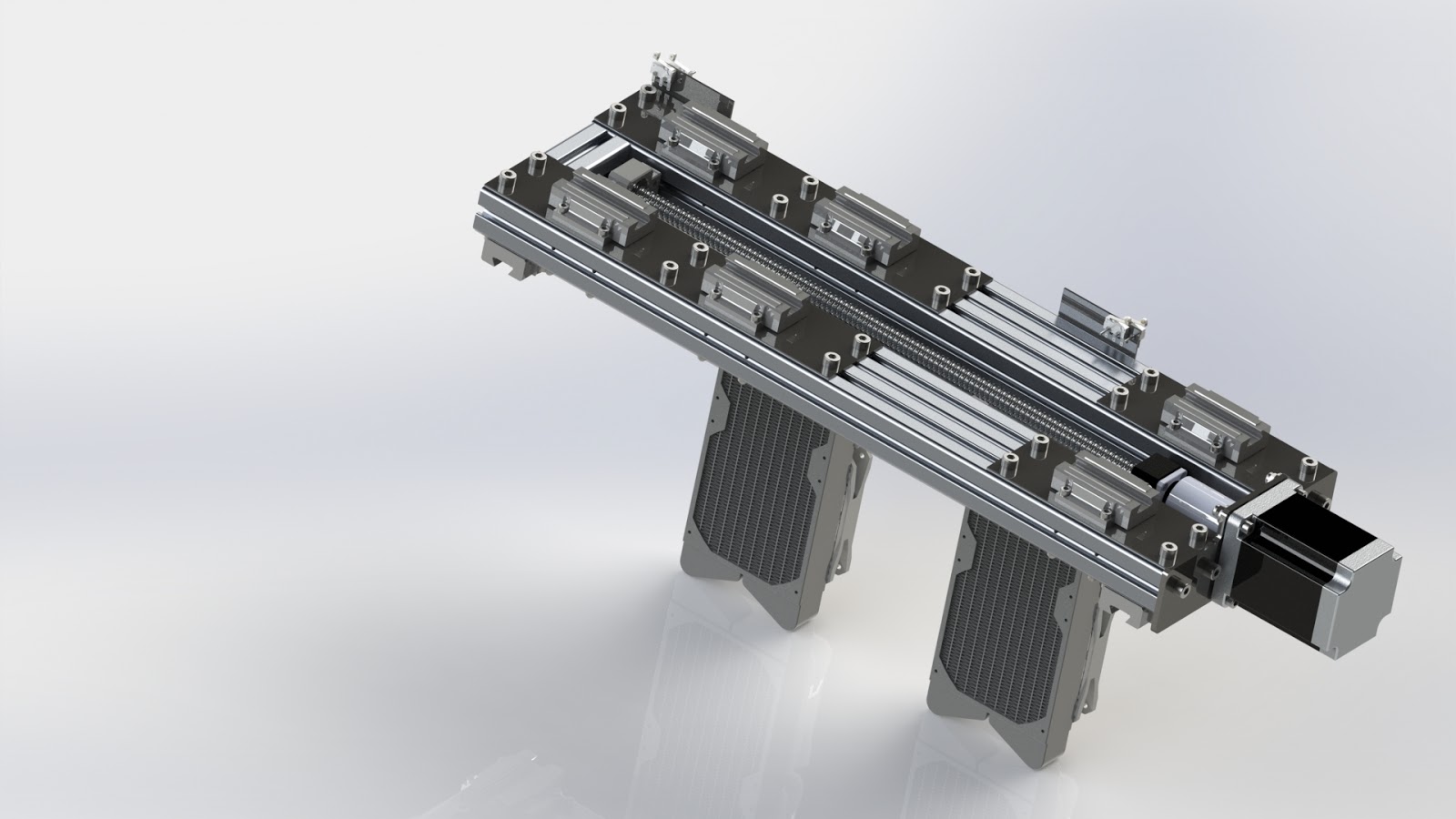
| X Axis |
I also used some carbon steal plates to make the aluminum profiles more solid.
About the double 40x40 aluminum profiles... I have no good explanation why I didn't use 40x80 instead. Maybe it sounds crazy but I kind of wanted to use only the same type of profiles... Also when I looked at the 40x80 profile to me it seamed to have less aluminum than two times 40x40.
Theoretical weight of the X axis is 61kg.
Main dimensions:
The Y axis looks like this because of the Z axis. I wanted Z to have at least 400mm length but most of the parts I will actually cut will be plates max 50mm so for this purpose the Y axis assembly has ten linear bearings on it. Again... I believe that the extra cost is worth it (you don't build a CNC every second week)
The fans are for the spindle. It may sound crazy but I'm building my CNC in my apartment, so because I don't want to disturb my neighbors i went for the liquid spindle. I need also to build a support for the tank. But I will figure this out later (hope I have space for it in here).
Theoretical weight of the Y axis is 15kg.
Main dimensions:
The Z Axis is more or less a carbon steel 5mm plate with who guide bars on which I installed the spindle. I hope it will not bend. I f this will happen then I will weld some other plates for reinforcement on it.
I have some other ideas with it (install a camera and other stuff) but for now this will have to do.
Theoretical weight of the Z axis is 10kg.
Main dimensions:
About the double 40x40 aluminum profiles... I have no good explanation why I didn't use 40x80 instead. Maybe it sounds crazy but I kind of wanted to use only the same type of profiles... Also when I looked at the 40x80 profile to me it seamed to have less aluminum than two times 40x40.
Theoretical weight of the X axis is 61kg.
Main dimensions:
- length = 1553mm
- width = 225mm
- height = 1242mm
  |
| Y Axis |
The fans are for the spindle. It may sound crazy but I'm building my CNC in my apartment, so because I don't want to disturb my neighbors i went for the liquid spindle. I need also to build a support for the tank. But I will figure this out later (hope I have space for it in here).
Theoretical weight of the Y axis is 15kg.
Main dimensions:
- length = 792mm
- width = 225mm
- height = 365mm
  |
| Z Axis |
I have some other ideas with it (install a camera and other stuff) but for now this will have to do.
Theoretical weight of the Z axis is 10kg.
Main dimensions:
- length = 1050mm (counting spindle)
- width = 214mm
- height = 159mm
No comments:
Post a Comment